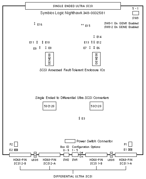
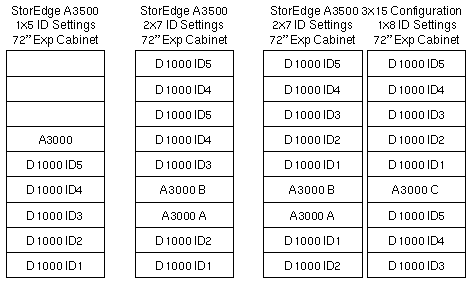
Differential SCSI Controller
StorEdge D1000
| 375-0008 |
| Symbios Nighthawk |

Notes
- The minimum operating system is Solaris 2.5.1 Hardware: 8/97.
- There are no pins at E3, E6, E7, E8, E9, E10, E11, E12, E13, or E14.
SW1 Switch Settings
| DIP |
SETTING |
DESCRIPTION |
| 1 |
Up * |
Right Array 1 drive addresses 8-13 (default) |
| 1 |
Down |
Right Array 1 drive addresses 0-5 |
| 2 |
Up |
Left Array 2 drive addresses 8-13 |
| 2 |
Down |
Left Array 2 drive addresses 0-5 (default) |
| 3 |
Up |
Wait for start unit command |
| 3 |
Down |
Use SW1-4 setting (default) |
| 4 |
Up |
Delayed start 12 sec × drive id (default) |
| 4 |
Down |
Start at power-on |
| 5 |
Up/Down |
Reserved for future use |
* Up = On, Down = Off
SW2 Rotary Switch Settings
Rotary Switch SW2 sets the Module ID of the StorEdge D1000.

Notes
- The board is installed solder side up in the StorEdge D1000.
- SW1 switch setting Up is toward the solder side of the board.
- SW1 switch setting Down is toward the component side of the board.
Reference
 A1000 and D1000 Installation, Operation, and Service, 805-2624.
 A3500 Hardware Configuration Guide, 805-4981.
|

