Sun Microsystems, Inc.
spacer spacer
spacer   Sun System Handbook Home | Systems | Components | General Info | Search | Feedback 
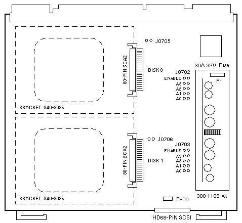
spacer
black dot
 
black fade
 

Disk Card

E4000 / E5000 / E6000 / E4500 / E5500 / E6500

Options 5161 / 5162 / 5163 / 5164

Option 5161 Option 5162 Option 5163 Option 5164
2 × 2.1GB Disks
7200 RPM
0GB FRU 501-3113
Disk FRU 540-2936
Disk FRU 540-2730
2 × 4.2GB Disks
7200 RPM
0GB FRU 501-3113
Disk FRU 540-2938
2 × 9.1GB Disks
7200 RPM
0GB FRU 501-3113
Disk FRU 540-3704
2 × 18.2GB Disks
10000 RPM
0GB FRU 501-3113
Disk FRU 540-4177
Assembly 501-4168 Assembly 501-5137 Assembly 501-5584 Assembly 501-5761

E4000, E5000, E4500, and E5500 Notes

  1. Up to four Disk Boards are supported.
  2. Install the Disk Board in any slot.
  3. The 4.2GB disk drive requires Disk Board >=501-3113-03.
  4. Disk Drives may fail to power up on Disk Board <=501-3113-02.

E6000 and E6500 Notes

  1. Up to two Disk Boards are supported.
  2. Install the Disk Board in Slot 14 and Slot 15 only.
  3. The 4.2GB disk drive requires Disk Board >=501-3113-03.
  4. Disk Drives may fail to power up on Disk Board <=501-3113-02.
  5. Install the Disk Board in Slot 15 if only one board is installed.

Default Drive Address Settings

The default drive address settings are assigned by the centerplane slot position when a jumper is not installed on J0702 and J0703 Pins 1-2.

SLOT DISK 0
ADDRESS
DISK 1
ADDRESS

SLOT DISK 0
ADDRESS
DISK 1
ADDRESS
0
1
2
3
4
5
6
7
4
6
0
10
2
12
8
14
5
7
1
11
3
13
9
15

8
9
10
11
12
13
14
15
10
0
12
2
14
8
0
10
11
1
13
3
15
9
1
11

Jumper Settings

Jumpers J0702 and J0703 override the default drive address settings assigned by the centerplane.

JUMPER PINS SETTING DESCRIPTION
J0702 1-2
1-2
A0-A3
Out
In
As required
Disk 0 default address selection
Disk 0 manual address selection
Disk 0 address select
J0703 1-2
1-2
A0-A3
Out
In
As required
Disk 1 default address selection
Disk 1 manual address selection
Disk 1 address select
J0705 1-2 As required Disk 0 delay spin
J0706 1-2 As required Disk 1 delay spin

Notes

  1. Disk Board FRU 501-3113 does not include disk drives.
  2. 10000 RPM disk drives require Disk Board >=501-3113-05.
  3. The normal LED pattern is On-Off-On prior to Solaris 2.6 HW 5/98.
  4. The normal LED pattern is Off-On-Off in Solaris >=2.6 HW 5/98.

References

  1. Ultra Enterprise 4000/5000/6000 System Manual, 802-3845.
  2. Enterprise 4500/5500/6500 System Reference Manual, 805-2632.

WebToneWebToneWebToneWebTone
 Copyright 1994-2003 Sun Microsystems, Inc.,  901 San Antonio Road, Palo Alto, CA 94303 USA.  All rights reserved.
 Legal Terms Privacy Policy Feedback