VX and MVX Visualization Accelerators
Board Set
501-1537 / 501-1538
Note
- Tighten Frontplane Connector screws 1, 2, 3, and 4 in sequence, turning
each screw no more than two turns at a time.
Notes
- The minimum operating system is SunOS 4.1.1.
- The final unbundled software release was SunVision 1.2.
- The minimum operating system for SunVision 1.2 is SunOS 4.1.2.
- SunVision 1.2 requires OpenWindows Version 3.
- The Sun 4300 CPU and the Sun 4400 CPU require EPROM 4.1.1
when the VX is used as the system console.
- Set the NVRAM locations to the values shown below when the VX is
used as the system console.
| LOCATION |
SETTING |
0x1f
0x60c
0x60d
0x60e
0x60f
0x610
0x611
0x612
0x613 |
12
31
40
00
00
fc
00
00
00 |
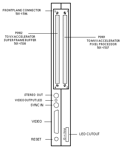
- Do not use Frontplane Connector 501-1596-01. Use 501-1596-02.
- The LEDs on the MVX are not used.
References
- Hardware Installation for the VX and MVX Visualization Accelerators, 800-5424-10.
- Software Installation for the VX and MVX Visualization Accelerators, 800-6290-10.
Super Frame Buffer
Sun-4/330/370/390/470/490
501-1538
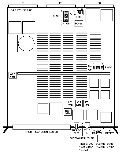
Power:
- 14.0 Amps @ +5Vdc
- 1.45 Amps @ -5Vdc
- 88.0 Watts
Switch Settings
Interrupt Request Switch S0101
| SWITCH |
SETTING |
REQUEST BIT |
1
2
3
4 |
Up
Down
Down
Up |
2
1
0
VMRQ |
VME Bus Address Switch S0102
| SWITCH |
SETTING |
ADDRESS BIT |
1
2
3
4
5
6
7
8 |
On
On
Off
Off
On
On
On
On/Off |
A31
A30
A29
A28
A27
A26
A25
Not used |
VX Bus Address Switch S0301
| SWITCH |
SETTING |
ADDRESS BIT |
1
2
3
4
5
6
7
8 |
On/Off
On/Off
On
On
On
On
On
On |
Not used
Not used
A26
A27
A28
A29
A30
A31 |
MVX Visualization Accelerator
Sun-4/330/370/390/470/490
Pixel Processor
501-1537
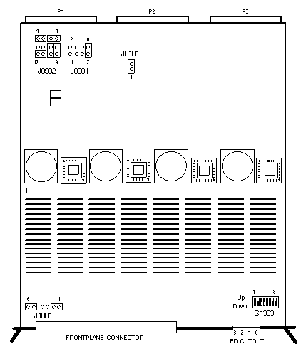
Power:
- 14.0 Amps @ +5Vdc
- 70.0 Watts
Switch and Jumper Settings
Clock Jumper J0101
| PIN |
SETTING |
DESCRIPTION |
| 1-2 |
In |
Enable 80MHz clock |
Bus Request Jumper J0901
| PIN |
SETTING |
DESCRIPTION |
3-4
5-6
7-8 |
In
Out
In |
VME BUS REQUEST 1
VME BUS REQUEST 2
VME BUS REQUEST 3 |
Bus Grant Jumper J0902
| PIN |
SETTING |
DESCRIPTION |
1-2
3-4
5-9
6-10
7
8
11-12 |
In
In
In
In
Out
Out
In |
BG2 OUT - BG2 IN
BG1 OUT - BG1 IN
BGx OUT - BG3 OUT
BGx IN - BG3 IN
BGx OUT
BGx IN
BG0 OUT - BG0 IN |
Bus Control and Arbitration Jumper J1001
| PIN |
SETTING |
DESCRIPTION |
1-2
3
4
5-6 |
In
Out
Out
In |
VCC - CTRL
GND
VCC
GND - MODE |
Base Address Switch S1303
| SWITCH |
SETTING |
ADDRESS BIT |
1
2
3
4
5
6
7
8 |
Down
Down
Up
Up
Down
Up
Down
Down/Up |
A31
A30
A29
A28
A27
A26
A25
Not used |
Last updated: December 2, 1996
|