|
BIOS/Flash Setting & Programming |
|
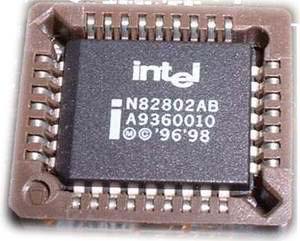
| Programming the BIOS on Willem enhanced programmer is easy, as long as we selected right chip type and right jumper. Here is an example for programming on a N82802AB of Intel845 mother board(3.3V): Note: when programming N82802AB chip, a 12V programming voltage is needed. So, to privent chip damaged by hi-voltage, please enable the Safety Protection Jumper. |
|
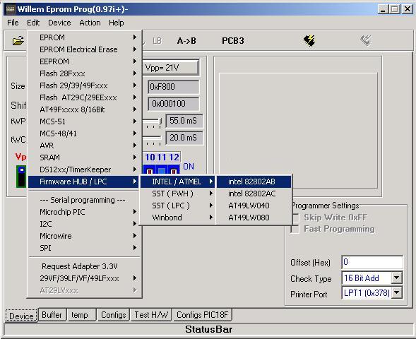
| 1, select chip type and software setting |
|
|
|
|
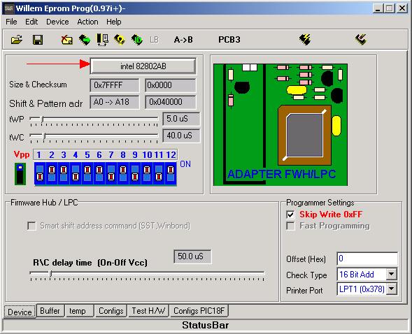
| now you can see following setting: | |
|
|
|
| DIP position:
OFF,ON,ON,OFF,ON,ON,OFF,ON,OFF,ON,OFF,ON |
|
| Chip's parameter is showed below
the Chip Select Button. Normaly, those parameters
are no need to adjusted, using default value. Size&checksum: shows chip's capacity and data buffer's checksum. Shift&pattem adress: shows chip's address line to be used and highest address bit. tWP/WC: shows programming pulse width and delay time. |
|
| 2. check chip's position After DIP set, check the chip's position. For BIOS chip, it should be placed in the 32 pins ZIF socket. For N82802AB chip, the program prompt user need a FWH/LPC adaptor. We only need put chip in the buld-in on board adaptor when using our Willem enhanced programmer. |
|
| Please make sure the pin one position on the FWH/LPC adaptor. |
|
| Note: 1,Displayed
chip's parameter is no need to be ajusted. 2, DIP is different when programming different chip 3, For EPROM chip, we need resetting the DIP, speicial chip and special valtage follow the prompt of software. |
|
| 3, read from chip After selected the chip, we can click on the "Read" button. All data will be put into the buffer. When reading the chip, the yellow LED will be light up, indicats that the valtage is been applied on the chip. |
|
|
|
|
| 4, Programming After insert the chip, click on "Open file" to open your
data file. Then click on "Programm Chip" button. Note,
some of chip need erase before write. |
|
|
|
|
|
|
|
| 5, copy a
chip: 2), "read" the data into buffer. 3), Put in the target chip and then click "Programm Chip". |
|
| Note: the chip may be damaged if wrong chip type selectd or chip in a wrong direction in socket. | |
| The following parameter is for advanced user only. | |
|
|
|
| R/C delay time: programming pulse delay. If your computer is too fast, you may need increase the delay. Skip Write 0xFF: Enable this setting will skip the 0xFF
when programming. |
|