EPROM Chip Programming
| The operation to EPROM chip is similar to general BIOS chip. The main diffrence is: the programmer jumper needs relevant ground setup. As an example: write a 27C16(programming voltage is 12.5V): |
|
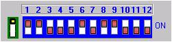
| 1. Select the chip and configuration Press chip selection button to select the right chip model, the program displays the DIP switch adjustment figure. Follow the figure to set up the DIP switch, includes the jumper next to DIP switch.
|
|
|
|
|
| The DIP switch setup is: toward to upper side is on, toward to bottom side is off. As to above figure, the DIP switch is: ON, ON, OFF, OFF, OFF, ON, OFF, ON, ON, OFF, OFF, OFF.
|
|
| 2. Fix the chip position After DIP switch set-up, insert the chip to 32 PIN
ZIF socket, meanwhile, special chip and special voltage setup button
shows rhe relevant chip parameters. |
|
| For the chips have capacity less than 1M, PIN fewer than 32 PIN, the chip installation is shown the right figure, align with the bottom of ZIF socket: |
|
|
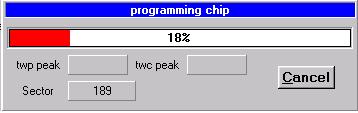
The follows operation is read in data file, programming. When programming, the red indicator lights up. This shows the programmer has corect voltage Vpp.
|
|
|
|
|
| Note:if wrongly select the chip model or wrongly the chip, the EPROM chip may be damaged. |
|