STREAMS Multiplex Drivers
This chapter describes how STREAMS multiplexing configurations are created and also discusses multiplexing drivers. A STREAMS multiplexer is a driver with multiple streams connected to it. The primary function of the multiplexing driver is to switch messages among the connected streams. Multiplexer configurations are created from the user level by system calls.
This chapter contains the following information:
STREAMS Multiplexers
STREAMS-related system calls are used to set up the "plumbing," or stream interconnections, for multiplexing drivers. The subset of these calls that allows a user to connect (and disconnect) streams below a driver is referred to as multiplexing. This type of connection is referred to as a one-to-M, or lower, multiplexer configuration. This configuration must always contain a multiplexing driver, which is recognized by STREAMS as having special characteristics.
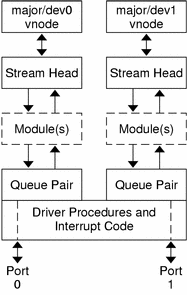
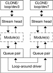
Multiple streams can be connected above a driver by open(2) calls. This accommodates the loop-around driver and the driver that handled multiple minor devices in Chapter 9, STREAMS Drivers. There is no difference between the connections to these drivers. Only the functions performed by the driver are different. In the multiplexing case, the driver routes data between multiple streams. In the device driver case, the driver routes data between user processes and associated physical ports. Multiplexing with streams connected above is referred to as an N-to-1, or upper, multiplexer. STREAMS does not provide any facilities beyond open and close to connect or disconnect upper streams for multiplexing.
From the driver's perspective, upper and lower configurations differ only in the way they are initially connected to the driver. The implementation requirements are the same: route the data and handle flow control. All multiplexer drivers require special developer-provided software to perform the multiplexing data routing and to handle flow control. STREAMS does not directly support flow control among multiplexed streams. M-to-N multiplexing configurations are implemented by using both of these mechanisms in a driver.
As discussed in Chapter 9, STREAMS Drivers, the multiple streams that represent minor devices are actually distinct streams in which the driver keeps track of each stream attached to it. The STREAMS subsystem does not recognize any relationship between the streams. The same is true for STREAMS multiplexers of any configuration. The multiplexed streams are distinct and the driver must be implemented to do most of the work.
In addition to upper and lower multiplexers, more complex configurations can be created by connecting streams containing multiplexers to other multiplexer drivers. With such a diversity of needs for multiplexers, providing general-purpose multiplexer drivers is not possible. Rather, STREAMS provides a general purpose multiplexing facility. The facility enables you to set up the intermodule or driver plumbing to create multiplexer configurations of generally unlimited interconnection.
Building a Multiplexer
The example in this section builds a protocol multiplexer with the multiplexing configuration shown in Figure 13-1. To free users from the need to know about the underlying protocol structure, a user-level daemon process is built to maintain the multiplexing configuration. Users can then access the transport protocol directly by opening the transport protocol (TP) driver device node.
An internetworking protocol driver (IP) routes data from a single upper stream to one of two lower streams. This driver supports two STREAMS connections beneath it. These connections are to two distinct networks; one for the IEEE 802.3 standard through the 802.3 driver, and another to the IEEE 802.4 standard through the 802.4 driver. The TP driver multiplexes upper streams over a single stream to the IP driver.
Figure 13-1 Protocol Multiplexer

Example 13-1 shows how this daemon process sets up the protocol multiplexer. The necessary declarations and initialization for the daemon program follow.
This multilevel multiplexed stream configuration is built from the bottom up. The example begins by first constructing the IP multiplexer. This multiplexing device driver is treated like any other software driver. It owns a node in the Solaris file system and is opened just like any other STREAMS device driver.
The first step is to open the multiplexing driver and the 802.4 driver, thus creating separate streams above each driver as shown in Figure 13-2. The stream to the 802.4 driver may now be connected below the multiplexing IP driver using the I_LINK ioctl(2).
Figure 13-2 Streams Before Link

The sequence of instructions to this point is:
	if ((fd_802_4 = open("/dev/802_4", O_RDWR)) < 0) {
			perror("open of /dev/802_4 failed");
			exit(1);
		}
		if ((fd_ip = open("/dev/ip", O_RDWR)) < 0) {
			perror("open of /dev/ip failed");
			exit(2);
		}
		/* now link 802.4 to underside of IP */
		if (ioctl(fd_ip, I_LINK, fd_802_4) < 0) {
			perror("I_LINK ioctl failed");
			exit(3);
		}
|
I_LINK takes two file descriptors as arguments. The first file descriptor, fd_ip, is the stream connected to the multiplexing driver, and the second file descriptor, fd_802_4, is the stream to be connected below the multiplexer. The complete stream to the 802.4 driver is connected below the IP driver. The stream head's queues of the 802.4 driver are used by the IP driver to manage the lower half of the multiplexer.
I_LINK returns an integer value, muxid, which is used by the multiplexing driver to identify the stream just connected below it. muxid is ignored in the example, but it is useful for dismantling a multiplexer or routing data through the multiplexer. Its significance is discussed in "Dismantling a Multiplexer".
The following sequence of system calls continues building the Internetworking Protocol multiplexer (IP):
	if ((fd_802_3 = open("/dev/802_3", O_RDWR)) < 0) {
			perror("open of /dev/802_3 failed");
			exit(4);
		}
		if (ioctl(fd_ip, I_LINK, fd_802_3) < 0) {
			perror("I_LINK ioctl failed");
			exit(5);
		}
|
The stream above the multiplexing driver used to establish the lower connections is the controlling stream and has special significance when dismantling the multiplexing configuration. This is illustrated in "Dismantling a Multiplexer". The stream referenced by fd_ip is the controlling stream for the IP multiplexer.
The order in which the streams in the multiplexing configuration are opened is unimportant. If intermediate modules in the stream are necessary between the IP driver and media drivers, these modules must be added to the streams associated with the media drivers (using I_PUSH) before the media drivers are attached below the multiplexer.
The number of streams that can be linked to a multiplexer is restricted by the design of the particular multiplexer. The manual page describing each driver describes such restrictions (see SunOS Reference Manual, Intro(7)) . However, only one I_LINK operation is allowed for each lower stream; a single stream cannot be linked below two multiplexers simultaneously.
Continuing with the example, the IP driver is now linked below the transport protocol (TP) multiplexing driver. As seen in Figure 13-1, only one link is supported below the transport driver. This link is formed by the following sequence of system calls:
	if ((fd_tp = open("/dev/tp", O_RDWR)) < 0) {
			perror("open of /dev/tp failed");
			exit(6);
		}
		if (ioctl(fd_tp, I_LINK, fd_ip) < 0) {
			perror("I_LINK ioctl failed");
			exit(7);
		}
|
Because the controlling stream of the IP multiplexer has been linked below the TP multiplexer, the controlling stream for the new multilevel multiplexer configuration is the stream above the TP multiplexer.
At this point, the file descriptors associated with the lower drivers can be closed without affecting the operation of the multiplexer. If these file descriptors are not closed, all subsequent read(2), write(2), ioctl(2), poll(2), getmsg(2), and putmsg(2) calls issued to them fail. That is because I_LINK associates the stream head of each linked stream with the multiplexer, so the user may not access that stream directly for the duration of the link.
The following sequence of system calls completes the daemon example:
	close(fd_802_4);
		close(fd_802_3);
		close(fd_ip);
		/* Hold multiplexer open forever or at least til this process
      is terminated by an external UNIX signal */
		pause();
	}
|


