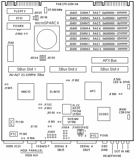
SPARCstation 5
SS5-70 / Netra i5
| 501-2286 |
501-2472 |
501-2508 |
70MHz 0MB FRU
2.3/2.5 microSPARC II |
70MHz 16MB
2.3/2.5 microSPARC II |
70MHz 32MB
2.3/2.5 microSPARC II |
|
| 501-2798 |
501-2802 |
501-2811 |
70MHz 0MB FRU
microSPARC II* |
70MHz 16MB
microSPARC II* |
70MHz 32MB
microSPARC II* |
* The chronological revision is 3.2, 3.3, 4.0.2, 2.6, and 2.6.2
Jumper Settings
Jumpers J0103 and J0104 set the microSPARC II memory controller wait states.
Wait states are used to maintain the memory timing requirements of 60ns DRAM.
| JUMPER |
PINS |
SETTING |
DESCRIPTION |
J0103
J0104 |
1-2
1-2 |
In*
In* |
spd_sel<0> = 0 (70MHz)
spd_sel<1> = 0 (70MHz) |
J0103
J0104 |
1-2
1-2 |
Out
In |
spd_sel<0> = 0 (85MHz)
spd_sel<1> = 1 (85MHz) |
J0103
J0104 |
1-2
1-2 |
In
Out |
spd_sel<0> = 1 (100MHz)
spd_sel<1> = 0 (100MHz) |
J0103
J0104 |
1-2
1-2 |
Out
Out |
spd_sel<0> = 1 (125MHz)
spd_sel<1> = 1 (125MHz) |
|
| * Default setting for the 70MHz CPU |
Jumpers J0105 and J0106 set the divide control bits used by the microSPARC II.
Set the 70MHz microSPARC II to divide by three to obtain an SBus speed of
23.33MHz.
| JUMPER |
PINS |
SETTING |
DESCRIPTION |
J0105
J0106 |
1-2
1-2 |
In
In |
div_ctl <0> = 0 /2
div_ctl <1> = 0 /2 |
J0105
J0106 |
1-2
1-2 |
Out*
In* |
div_ctl <0> = 1 /3
div_ctl <1> = 0 /3 |
J0105
J0106 |
1-2
1-2 |
In
Out |
div_ctl <0> = 0 /4
div_ctl <1> = 1 /4 |
J0105
J0106 |
1-2
1-2 |
Out
Out |
div_ctl <0> = 1 /5
div_ctl <1> = 1 /5 |
|
| * Default setting for the 70MHz CPU |
| JUMPER |
PINS |
SETTING |
DESCRIPTION |
| J0100 |
1-2 |
Out |
Pin-1=Gnd / Pin-2=POK |
| J1101 |
1-2
1-2 |
Out
In |
1= normal (default)
0= -4.5db |
| J1102 |
1-2
1-2 |
Out
In |
1=100 Ohm (default)
0=150 Ohm |
| J1005 |
1-2
3-4
5-6
7-8 |
Out
Out
Out
Out |
Test point tpe<0>
Test point tpe<1>
Test point tpe<2>
Test point tpe<3> |
J1602
J1603
J1602
J1603 |
1-2
1-2
2-3
2-3 |
In
In
In
In |
Select RS-423 (default)
Select RS-423 (default)
Select RS-232 (-12Vdc)
Select RS-232 (+12Vdc) |
| J1604 |
1-2
3-4
5-6
7-8 |
Out
Out
Out
Out |
Test point rxda
Test point txda
Test point rxdb
Test point txdb |
| J1900 |
N/A |
N/A |
Ground test point |
| J1901 |
N/A |
N/A |
Ground test point |
| J1902 |
N/A |
N/A |
Ground test point |
| J1903 |
N/A |
N/A |
Ground test point |
| J1904 |
N/A |
N/A |
Ground test point |
| J1905 |
N/A |
N/A |
Ground test point |
| J1906 |
N/A |
N/A |
Ground test point |
Notes
- The minimum OS is Solaris 1.1.1 Version B or Solaris 2.3 Edition II.
- SS5 audio requires the Solaris 1.1.1 Version B ms2 patch.
- Install the highest capacity SIMM in Slot 0 under Solaris 1.x.
- Use the MFAR value to determine the address of a failing SIMM.
- The PLCC Boot PROM is not a FRU and is not field replaceable.
- Serial Ports A and B support synchronous operation.
Reference
 SPARCstation 5 Service Manual, 801-6396.
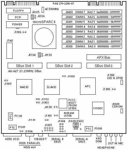
SS5-85 / Netra i5 / Netra s5
| 501-2572 |
501-2574 |
501-2799 |
501-2803 |
85MHz 0MB FRU
2.3/2.5 microSPARC II |
85MHz 32MB
2.3/2.5 microSPARC II |
85MHz 0MB FRU
3.x microSPARC II |
85MHz 32MB
3.x microSPARC II |

Power
- 0MB Board
- 4.0 Amps @ +5Vdc
- 0.4 Amps @ +12Vdc
- 0.1 Amps @ -12Vdc
- 8.0 Watts
SS5-85 / Netra i5 / Netra s5
| 501-2815 |
501-2816 |
85MHz 0MB FRU
microSPARC II * |
85MHz 32MB
microSPARC II * |
* The chronological revision of microSPARC II is 2.6 and 2.6.2.
Power
- 0MB Board
- 4.0 Amps @ +5Vdc
- 0.4 Amps @ +12Vdc
- 0.1 Amps @ -12Vdc
- 8.0 Watts
501-2572 / 501-2574 / 501-2799 / 501-2803 / 501-2815 / 501-2816
Jumper Settings
Jumpers J0103 and J0104 set the microSPARC II memory controller wait states.
Wait states are used to maintain the memory timing requirements of 60ns DRAM.
| JUMPER |
PINS |
SETTING |
DESCRIPTION |
J0103
J0104 |
1-2
1-2 |
In
In |
spd_sel<0> = 0 (70MHz)
spd_sel<1> = 0 (70MHz) |
J0103
J0104 |
1-2
1-2 |
Out*
In* |
spd_sel<0> = 0 (85MHz)
spd_sel<1> = 1 (85MHz) |
J0103
J0104 |
1-2
1-2 |
In
Out |
spd_sel<0> = 1 (100MHz)
spd_sel<1> = 0 (100MHz) |
J0103
J0104 |
1-2
1-2 |
Out
Out |
spd_sel<0> = 1 (125MHz)
spd_sel<1> = 1 (125MHz) |
|
| * Default setting for the 85MHz CPU |
Jumpers J0105 and J0106 set the divide control bits used by the microSPARC
II. Set the 85MHz microSPARC II to divide by four to obtain an SBus speed of
21.25MHz.
| JUMPER |
PINS |
SETTING |
DESCRIPTION |
J0105
J0106 |
1-2
1-2 |
In
In |
div_ctl <0> = 0 /2
div_ctl <1> = 0 /2 |
J0105
J0106 |
1-2
1-2 |
Out
In |
div_ctl <0> = 1 /3
div_ctl <1> = 0 /3 |
J0105
J0106 |
1-2
1-2 |
In*
Out* |
div_ctl <0> = 0 /4
div_ctl <1> = 1 /4 |
J0105
J0106 |
1-2
1-2 |
Out
Out |
div_ctl <0> = 1 /5
div_ctl <1> = 1 /5 |
|
| * Default setting for the 85MHz CPU |
| JUMPER |
PINS |
SETTING |
DESCRIPTION |
| J0100 |
1-2 |
Out |
Pin-1=Gnd / Pin-2=POK |
| J1101 |
1-2
1-2 |
Out
In |
1= normal (default)
0= -4.5db |
| J1102 |
1-2
1-2 |
Out
In |
1=100 Ohm (default)
0=150 Ohm |
| J1005 |
1-2
3-4
5-6
7-8 |
Out
Out
Out
Out |
Test point tpe<0>
Test point tpe<1>
Test point tpe<2>
Test point tpe<3> |
J1602
J1603
J1602
J1603 |
1-2
1-2
2-3
2-3 |
In
In
In
In |
Select RS-423 (default)
Select RS-423 (default)
Select RS-232 (-12Vdc)
Select RS-232 (+12Vdc) |
| J1604 |
1-2
3-4
5-6
7-8 |
Out
Out
Out
Out |
Test point rxda
Test point txda
Test point rxdb
Test point txdb |
| J1900 |
N/A |
N/A |
Ground test point |
| J1901 |
N/A |
N/A |
Ground test point |
| J1902 |
N/A |
N/A |
Ground test point |
| J1903 |
N/A |
N/A |
Ground test point |
| J1904 |
N/A |
N/A |
Ground test point |
| J1905 |
N/A |
N/A |
Ground test point |
| J1906 |
N/A |
N/A |
Ground test point
|
Notes
- The minimum OS is Solaris 1.1.1 Version B or Solaris 2.3 Edition II.
- SS5 audio requires the Solaris 1.1.1 Version B ms2 patch.
- Install the highest capacity SIMM in Slot 0 under Solaris 1.x.
- Use the MFAR value to determine the address of a failing SIMM.
- The PLCC Boot PROM is not a FRU and is not field replaceable.
- Serial Ports A and B support synchronous operation.
Reference
-
SPARCstation 5 Service Manual, 801-6396.
SS5-110 / Netra i5 / Netra i500 / Netra i525
| 501-2778 |
501-2779 |
110MHz 0MB FRU
microSPARC II |
110MHz 32MB
microSPARC II |
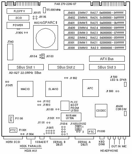
Power: 0MB Board
- 4.0 Amps @ +5Vdc
- 0.4 Amps @ +12Vdc
- 0.1 Amps @ -12Vdc
- 8.0 Watts
Jumper Settings
Jumpers J0103 and J0104 set the microSPARC II memory controller wait states.
Wait states are used to maintain the memory timing requirements of 60ns DRAM.
| JUMPER |
PINS |
SETTING |
DESCRIPTION |
J0103
J0104 |
1-2
1-2 |
In
In |
spd_sel<0> = 0 (70MHz)
spd_sel<1> = 0 (70MHz) |
J0103
J0104 |
1-2
1-2 |
Out
In |
spd_sel<0> = 0 (85MHz)
spd_sel<1> = 1 (85MHz) |
J0103
J0104 |
1-2
1-2 |
In*
Out* |
spd_sel<0> = 1 (110MHz)
spd_sel<1> = 0 (110MHz) |
J0103
J0104 |
1-2
1-2 |
Out
Out |
spd_sel<0> = 1 (125MHz)
spd_sel<1> = 1 (125MHz) |
|
| * Default setting for the 110MHz CPU |
Jumpers J0105 and J0106 set the divide control bits used by the microSPARC II.
Set the 110MHz microSPARC II to divide by five to obtain an SBus speed of
22.00MHz.
| JUMPER |
PINS |
SETTING |
DESCRIPTION |
J0105
J0106 |
1-2
1-2 |
In
In |
div_ctl <0> = 0 /2
div_ctl <1> = 0 /2 |
J0105
J0106 |
1-2
1-2 |
Out
In |
div_ctl <0> = 1 /3
div_ctl <1> = 0 /3 |
J0105
J0106 |
1-2
1-2 |
In
Out |
div_ctl <0> = 0 /4
div_ctl <1> = 1 /4 |
J0105
J0106 |
1-2
1-2 |
Out*
Out* |
div_ctl <0> = 1 /5
div_ctl <1> = 1 /5 |
|
| * Default setting for the 110MHz CPU |
| JUMPER |
PINS |
SETTING |
DESCRIPTION |
| J0100 |
1-2 |
Out |
Pin-1=Gnd / Pin-2=POK |
| J1101 |
1-2
1-2 |
Out
In |
1= normal (default)
0= -4.5db |
| J1102 |
1-2
1-2 |
Out
In |
1=100 Ohm (default)
0=150 Ohm |
| J1005 |
1-2
3-4
5-6
7-8 |
Out
Out
Out
Out |
Test point tpe<0>
Test point tpe<1>
Test point tpe<2>
Test point tpe<3> |
J1602
J1603
J1602
J1603 |
1-2
1-2
2-3
2-3 |
In
In
In
In |
Select RS-423 (default)
Select RS-423 (default)
Select RS-232 (-12Vdc)
Select RS-232 (+12Vdc) |
| J1604 |
1-2
3-4
5-6
7-8 |
Out
Out
Out
Out |
Test point rxda
Test point txda
Test point rxdb
Test point txdb |
| J1900 |
N/A |
N/A |
Ground test point
|
| J1901 |
N/A |
N/A |
Ground test point
|
| J1902 |
N/A |
N/A |
Ground test point
|
| J1903 |
N/A |
N/A |
Ground test point
|
| J1904 |
N/A |
N/A |
Ground test point
|
| J1905 |
N/A |
N/A |
Ground test point |
| J1906 |
N/A |
N/A |
Ground test point |
Notes
- The minimum OS is Solaris 1.1.1 Version B or Solaris 2.3 Edition II.
- SS5 audio requires the Solaris 1.1.1 Version B ms2 patch.
- Install the highest capacity SIMM in Slot 0 under Solaris 1.x.
- Use the MFAR value to determine the address of a failing SIMM.
- The PLCC Boot PROM is not a FRU and is not field replaceable.
- Serial Ports A and B support synchronous operation.
Reference
-
SPARCstation 5 Service Manual, 801-6396.
SS5-170 / Netra i 5 / Netra j 5/170
| 501-3059 |
501-3103 |
170MHz 0MB FRU
TurboSPARC II |
170MHz 32MB
TurboSPARC II |
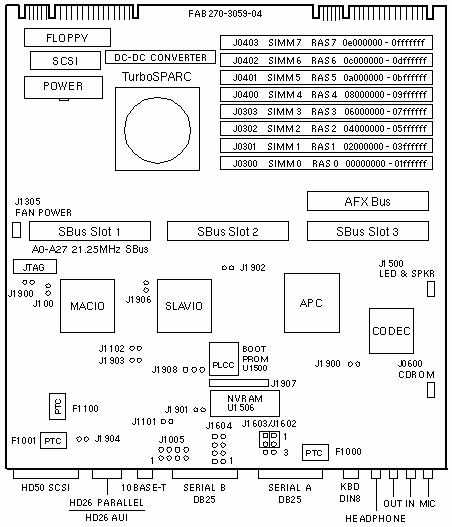
Jumper Settings
| JUMPER |
PINS |
SETTING |
DESCRIPTION |
| J0100 |
1-2 |
Out |
Pin-1=Gnd / Pin-2=POK |
| J1101 |
1-2
1-2 |
Out
In |
1= normal (default)
0= -4.5db |
| J1102 |
1-2
1-2 |
Out
In |
1=100 Ohm (default)
0=150 Ohm |
| J1005 |
1-2
3-4
5-6
7-8 |
Out
Out
Out
Out |
Test point tpe<0>
Test point tpe<1>
Test point tpe<2>
Test point tpe<3> |
J1602
J1603
J1602
J1603 |
1-2
1-2
2-3
2-3 |
In
In
In
In |
Select RS-423 (default)
Select RS-423 (default)
Select RS-232 (-12Vdc)
Select RS-232 (+12Vdc) |
| J1604 |
1-2
3-4
5-6
7-8 |
Out
Out
Out
Out |
Test point rxda
Test point txda
Test point rxdb
Test point txdb |
| J1900 |
N/A |
N/A |
Ground test point
|
| J1901 |
N/A |
N/A |
Ground test point
|
| J1902 |
N/A |
N/A |
Ground test point
|
| J1903 |
N/A |
N/A |
Ground test point
|
| J1904 |
N/A |
N/A |
Ground test point
|
| J1905 |
N/A |
N/A |
Ground test point |
| J1906 |
N/A |
N/A |
Ground test point |
| J1908 |
N/A |
N/A |
ROMBO Selection |
Notes
- The minimum OS is Solaris 1.1.1 Version B or Solaris 2.3 Edition II.
- SS5 audio requires the Solaris 1.1.1 Version B ms2 patch.
- SS5 S24 configurations require Solaris 2.3 Hardware: 8/94.
- Install the highest capacity SIMM in Slot 0 under Solaris 1.x.
- Use the MFAR value to determine the address of a failing SIMM.
- The PLCC Boot PROM is not a FRU and is not field replaceable.
- Serial Ports A and B support synchronous operation.
Reference
-
SPARCstation 5 Service Manual, 801-6396.
|