Ultra 450
A20
| 501-5028 |
| 0MB FRU w 2MB Cache Support |

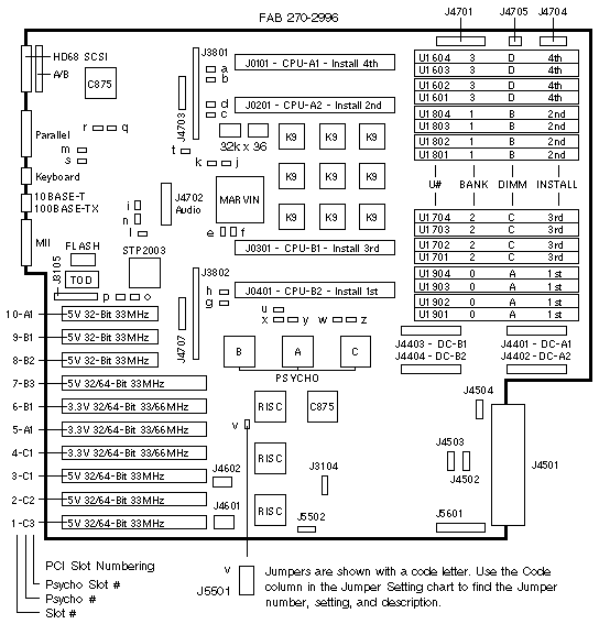
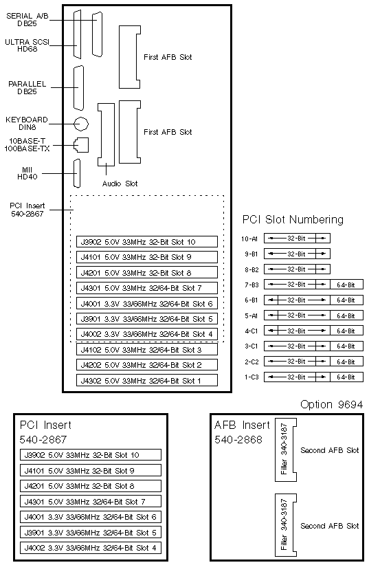
PCI Slot Numbering
| SILKSCREEN |
PCI
SLOT |
PSYCHO |
PCI BUS |
DEVICE TREE |
| 10-A1 |
10 |
PSYCHO A - SLOT 1 |
B - 0 |
pci@1f,4000/*@4,* |
| 9-B1 |
9 |
PSYCHO B - SLOT 1 |
F - 2 |
pci@4,4000/*@2,* |
| 8-B2 |
8 |
PSYCHO B - SLOT 2 |
F - 2 |
pci@4,4000/*@3,* |
| 7-B3 |
7 |
PSYCHO B - SLOT 3 |
F - 2 |
pci@4,4000/*@4,* |
| 6-B1 |
6 |
PSYCHO B - SLOT 1 |
E - 3 |
pci@4,2000/*@1,* |
| 5-A1 |
5 |
PSYCHO A - SLOT 1 |
A - 1 |
pci@1f,2000/*@1,* |
| 4-C1 |
4 |
PSYCHO C - SLOT 1 |
C - 5 |
pci@6,2000/*@1,* |
| 3-C1 |
3 |
PSYCHO C - SLOT 1 |
D - 4 |
pci@6,4000/*@2,* |
| 2-C2 |
2 |
PSYCHO C - SLOT 2 |
D - 4 |
pci@6,4000/*@3,* |
| 1-C3 |
1 |
PSYCHO C - SLOT 3 |
D - 4 |
pci@6,4000/*@4,* |
Psycho A and Psycho C share the address/data bus. Psycho B has a private bus.
PCI Bus B shares the address/data bus with onboard Audio, Ethernet, Flash,
Floppy, Keyboard, Mouse, NVRAM, Parallel, SCSI, and Serial devices.
Jumper Settings
| CODE |
JUMPER |
PINS |
SETTING |
DESCRIPTION |
| a |
J0102 |
2-3 |
In |
CPU-A1 scan enabled |
| b |
J0103 |
2-3 |
In |
UPA-A lab debug use only |
| c |
J0104 |
2-3 |
In |
UPA-A lab debug use only |
| d |
J0202 |
2-3 |
In |
CPU-A2 scan enabled |
| e |
J0302 |
2-3 |
In |
CPU-B1 scan enabled |
| f |
J0303 |
2-3 |
In |
UPA-B lab debug use only |
| g |
J0304 |
2-3 |
In |
UPA-B lab debug use only |
| h |
J0402 |
2-3 |
In |
CPU-B2 scan enabled |
| i |
J0501 |
2-3 |
In |
Marvin scan enabled |
| j |
J0601 |
2-3 |
In |
Marvin SRAM U0601 scan enabled |
| k |
J0602 |
2-3 |
In |
Marvin SRAM U0602 scan enabled |
| l |
J2304 |
2-3 |
In |
STP2003 scan enabled |
| m |
J2402 |
2-3 |
In |
53C825 SCSI J2401 scan enabled |
| n |
J2701 |
1-2
2-3 |
In/Out
In |
÷3 mode (250/300MHz) *
÷2 mode and ÷4 (400MHz) * |
| o |
J3102 |
1-2
2-3 |
In
In |
Select FPROM (default)
Select ROMBO |
| p |
J3103 |
1-2
2-3 |
In
In |
FPROM write protect
FPROM write enable (default) |
| q |
J3303 |
1-2
2-3 |
In
In |
RS-232
RS-423 (default) |
| r |
J3304 |
1-2
2-3 |
In
In |
RS-232
RS-423 (default) |
| s |
J3401 |
2-3 |
In |
Ethernet 83840 PHY scan enabled |
| t |
J3803 |
2-3 |
In |
FFB J3801 Port ID 0x1d scan enabled |
| u |
J3804 |
2-3 |
In |
FFB J3802 Port ID 0x1e scan enabled |
| v |
J5501 |
1-2
2-3 |
In
In |
FPROM flash recovery mode
FPROM normal booting (default) |
| w |
J5602 |
2-3 |
In |
53C825 SCSI J5601 scan enabled |
| x |
J5701 |
2-3 |
In |
Psycho B scan enabled |
| y |
J5702 |
2-3 |
In |
Psycho A scan enabled |
| z |
J5703 |
2-3 |
In |
Psycho C scan enabled |
* The "ULTRA-1 CPU 2-3" silkscreen is incorrect.
UltraSPARC I is not supported.
The 3-Pin header is not installed in system board <501-5028-02.
Miscellaneous Connectors
| CONNECTOR |
PINS |
DESCRIPTION |
| J3104 |
3 |
Button XIR (1-2) and POR (2-3) |
| J3105 |
32 |
ROMBO (factory use) |
| J3801 |
144 |
First UPA framebuffer * |
| J3802 |
144 |
Second UPA framebuffer * |
| J4401 |
40 |
DC-A1 DC-DC Converter for CPU-A1 |
| J4402 |
40 |
DC-A2 DC-DC Converter for CPU-A2 |
| J4403 |
40 |
DC-B1 DC-DC Converter for CPU-B1 |
| J4404 |
40 |
DC-B2 DC-DC Converter for CPU-B2 |
| J4501 |
144 |
Power from DC Distribution board |
| J4502 |
24 |
To wavecrimp connector J4501 |
| J4503 |
24 |
To wavecrimp connector J4501 |
| J4504 |
14 |
Not installed |
| J4601 |
30 |
Not installed after early production |
| J4602 |
4 |
Second AFB fan power (not used) |
| J4701 |
68 |
Ultra SCSI to removable media backplane |
| J4702 |
40 |
Audio Module * |
| J4703 |
20 |
First AFB power * |
| J4704 |
12 |
CPU Fan power |
| J4705 |
6 |
First AFB Blower power |
| J4707 |
20 |
Second AFB power * |
| J5502 |
8 |
JTAG Scan (6-8 jumpered) |
| J5503 |
6 |
Not installed |
| J5504 |
2 |
Not installed |
| J5601 |
68 |
Ultra SCSI to 4-slot disk backplane |
* J4703 and J4707 are not installed on 501-5270.
* J3801, J3802, J4702, J4703, J4707 are not installed on 501-5672.
* J3801, J3802, J4702, J4703, J4707 are not installed on 501-5673.
 The Wrench Icon is lit when Blower 540-3023 or
Loopback Plug 530-2509 is not connected to J4705 on the System Board.
AFB Blower 540-3023 was not installed after August 1997. The Wrench Icon is lit when Blower 540-3023 or
Loopback Plug 530-2509 is not connected to J4705 on the System Board.
AFB Blower 540-3023 was not installed after August 1997.
Backpanel Connectors and Backpanel Inserts

|
Ultra 450 Codename: Tazmo |
Notes
- The minimum A25 operating system is Solaris 2.5.1 Hardware: 4/97.
- The minimum A20 operating system is 2.5.1 HW: 11/97 or 2.6 HW: 3/98.
- The Ultra 450 workstation was sold from July 1998 to May 1999.
- Ultra Enterprise 450 was renamed Enterprise 450 in December 1997.
- Use the Flash PROM Programming Utility to update the flash PROM.
- Disconnect all system board power cables before removing or installing
the NVRAM. Failure to remove power can result in NVRAM corruption.
- Use the setenv mfg-options OBP command to set the system up as
a Server (mfg-options 49) or as a Workstation
(mfg-options 0).
Backpanel Insert Notes
- System Board FRUs include PCI Insert 540-2867.
- 64-Bit PCI boards do not fit into Slots 9 and 10 of system boards
501-5028, 501-2996, and 501-5270. Connectors J3802 and J4707
interfere with the 64-Bit PCI extension connector.
- J3802 and J4707 are not installed on 501-5672 or 501-5673.
- AFB Insert 540-2868 is required if a second AFB is installed.
- Three PCI Slots are available when the AFB Insert is installed.
Graphics Notes
- Creator and Creator 3D are not supported.
- System Board 501-2996 does not support Elite3D (AFB).
- AFB Power connectors are not on 501-5270, 501-5672, and 501-5673.
- System Board 501-5028 was shipped in servers
by Dev WO_14046
.
- Elite3D-m6 lower board <=501-4231-06 is not compatible with the A20.
- Elite3D-m6 assembly <=540-3058-06 is not compatible with the A20.
- The Wrench icon is lit when AFB Blower 540-3023 or Loopback Plug 530-2509
(Pin-1 to 2) is not connected to J4705 on the System Board.
- AFB Blower 540-3023 was not installed after August 1997.
- A maximum of three Expert3D boards may be installed.
- Each Expert3D requires Fan board 370-4272 in a lower, adjacent slot.
Module Notes
- Each UltraSPARC Module requires DC-DC Converter 300-1322.
- The installation sequence is different between FABs <=270-2996-03 and
>=270-2996-04 (04 to 10) and 270-2058.
- The 400MHz module requires OBP >=3.12 Version 1.
- Empty slot A1 requires Air Baffle 330-2781 or 330-2805 if 400MHz
modules are used. A Baffle is included with UGMB-A25AA-A25B.
- The 400MHz module is not approved for use in the Ultra 450.
- The 400MHz module is not compatible with System Board 501-2996.
- Systems built prior to approx. 11/98 are FCC Class A compliant with 400MHz.
- The 480MHz module requires OBP >=3.18 Version 0.
- Airduct 540-4597 is required when 480MHz modules are installed.
Module Slot Numbering
| SOCKETS |
UPA SLOT |
LABEL |
INSTALL |
OBP/OS |
DC-DC |
| J0101 |
1 |
CPU-A1 |
4th |
CPU 0 |
DC-A1 |
| J0202 |
2 |
CPU-A2 |
2nd |
CPU 1 |
DC-A2 |
| J0301 |
3 |
CPU-B1 |
3rd |
CPU 2 |
DC-B1 |
| J0401 |
4 |
CPU-B2 |
1st |
CPU 3 |
DC-B2 |
Memory Notes
- Four DIMMs of the same size form a bank.
- The installation sequence is AAAA, BBBB, CCCC, and DDDD.
- Use the setenv memory-interleave OBP command to override
the default interleave setting of auto.
- The smallest DIMM size is used and the remaining memory is lost
if interleaving is enabled and the bank sizes are different.
Memory Slot Numbering
| SOCKET |
LABEL |
INSTALL |
BANK |
DIMM# |
ADDRESS |
U1604
U1603
U1602
U1601 |
D
D
D
D
|
4th
4th
4th
4th |
3
3
3
3 |
3
2
1
0 |
c000 0000 - ffff ffff
c000 0000 - ffff ffff
c000 0000 - ffff ffff
c000 0000 - ffff ffff |
U1804
U1803
U1802
U1801 |
B
B
B
B
|
2nd
2nd
2nd
2nd |
1
1
1
1 |
3
2
1
0 |
4000 0000 - 7fff ffff
4000 0000 - 7fff ffff
4000 0000 - 7fff ffff
4000 0000 - 7fff ffff |
U1704
U1703
U1702
U1701 |
C
C
C
C
|
3rd
3rd
3rd
3rd |
2
2
2
2 |
3
2
1
0 |
8000 0000 - bfff ffff
8000 0000 - bfff ffff
8000 0000 - bfff ffff
8000 0000 - bfff ffff |
U1904
U1903
U1902
U1901 |
A
A
A
A
|
1st
1st
1st
1st |
0
0
0
0 |
3
2
1
0 |
0000 0000 - 3fff ffff
0000 0000 - 3fff ffff
0000 0000 - 3fff ffff
0000 0000 - 3fff ffff |
SCSI Bus Notes
- The RMA Backplane is controlled by /pci@1f,4000/scsi@2.
- The 4-Slot Disk Backplane is controlled by /pci@1f,4000/scsi@3.
- The external A20/A25 SCSI bus is controlled by /pci@1f,4000/scsi@2.
Reference
 Ultra Enterprise 450 Owners Guide, 805-0429.
 Ultra 450 Owners Guide, 805-0430.
 Flash PROM Programming Guide, 802-3233.
|


 The Wrench Icon is lit when Blower 540-3023 or
Loopback Plug 530-2509 is not connected to J4705 on the System Board.
AFB Blower 540-3023 was not installed after August 1997.