Sun LX50 LEDs
System Status LED

| System Status LED State |
System Condition |
| Continuous Green |
System is operating normally |
| Blinking Green |
System is operating in degraded condition |
| Blinking Amber |
System is in a non critical condition |
| Continuous Amber |
System is in a critical condition |
| No Light |
POST/system stop |
Critical Condition
A critical condition or non-recoverable threshold crossing is associated with
the following events:
- Temperature, voltage, or fan critical threshold crossing.
- Power subsystem failure. The Baseboard1 Management Controller (BMC) asserts
this failure whenever it detects a power control fault (for example, the BMC
detects that the system power is remaining on even though the BMC has deasserted
the signal to turn off power to the system).
- The system is unable to power up due to incorrectly installed processor(s),
or processor incompatibility.
- A satellite controller such as the HSC, or another IMPI-capable device, such
as an add-in server management PCI card, sends a critical or non-recoverable
state, via the Set Fault Indication command to the BMC.
- Critical Event Logging errors, including System Memory Uncorrectable ECC error
and Fatal/Uncorrectable Bus errors, such as PCI SERR and PERR.
Non-Critical Condition
A non-critical condition indicates that at least one of the following conditions
is present:
- Temperature, voltage, or fan non-critical threshold crossing.
- Chassis intrusion.
- Satellite controller sends a non-critical state, via the Set Fault Indication
command, to the BMC.
- A Set Fault Indication command from the system BIOS. The BIOS may use the Set
- Fault Indication command to indicate additional, non-critical status such as
system memory or CPU configuration changes.
Degraded Condition
A degraded condition indicates that at least one of the following conditions
is present:
- A processor is disabled by FRB or BIOS.
- BIOS has disabled or mapped out some of the system memory.
Power Supply Status LED

| Power Supply LED State |
Power Supply Condition |
| Off |
No AC power present to power supply |
| Blinking Green |
AC power present, but only the standby outputs are on |
| Green |
Power supply DC outputs on and OK |
| Blinking Amber |
PSAlert# signal asserted, power supply on |
| Amber |
Power supply shutdown due to over current, over temperature, fan failure,
over voltage, or undervoltage |
| Amber or Off |
Power supply failed and AC fuse open or other critical failure |
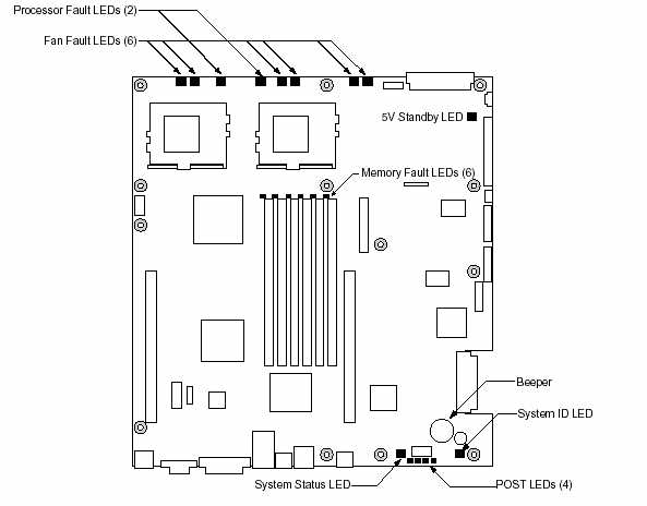
Server Main Board Fault LEDs

- POST Code LEDs: The server board includes an enhanced diagnostic
feature that consists of a hardware decoder and four LEDs located at the back
of the server board. As the BIOS tests specific areas, the code is displayed
at the onset of the BIOS routine. If the BIOS hangs, the display shows which
operation was in process.
- Processor Fault LEDs: A fault indicator LED is located next to each
of the processor sockets. If the server Baseboard Management Controller (BMC)
detects a fault in any processor, the corresponding LED illuminates.
- Memory Fault LEDs: A fault indicator LED is located next to each
of the DIMM sockets. If the BMC detects a fault in a given DIMM, the corresponding
LED illuminates.
- Fan Fault LEDs: A fault indicator LED is located next to each fan
header. When the BMC detects a fan fault, the corresponding LED illuminates.
If any fan fault LED is lit, the entire fan module must be replaced.
- System Status LED: Indicates functional status of the server board.
Glows green when all systems are operating normally. Glows amber when one
or more systems are in a fault status. This LED mirrors the function of the
system status LED on the front panel.
- +5 V Standby LED: This LED is on when the server is plugged into
AC power, whether or not the server is actually powered on.
System ID LED

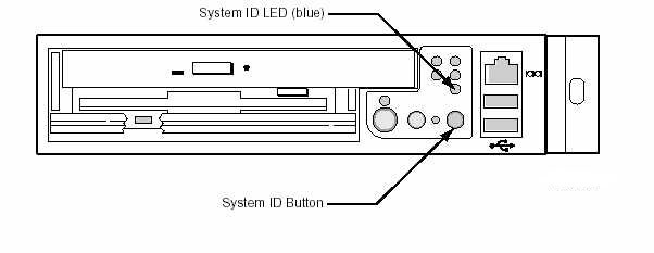
A pair of blue LEDs, one at the rear of the server, and one on the front panel,
can be used to easily identify the server when it is part of a large stack of
servers. A single blue LED located at the back edge of the server board next
to the backup battery is visible through the rear panel. The two LEDs mirror
each other and can be illuminated by the Baseboard Management Controller (BMC)
either by pressing a button on the chassis front panel or through servermanagement
software. When the button is pressed on the front panel, both LEDs illuminate
and stay illuminated until the button is pushed again. If the LED is illuminated
through a remote System Identify command, the LED turns off after a timeout
period.
Front Panel LEDs

- Power LED (green): This LED is controlled by software. It flashes
when the server is first powered up and changes to steady on when the server
firmware has completed the power-up self-test (POST).
- NIC1 and NIC2 LEDs (green): These LEDs blink to reflect network data
activity.
- System Status/Fault LED (green/amber): This LED can assume different
states (green, amber, steady, blinking) to indicate critical, non-critical,
or degraded server operation. See System Status LED
for more details regarding this LED.
- Hard Disk Drive Activity LED (green): The Drive Activity LED on the
front panel is used to indicate drive activity from the onboard SCSI controller.
The server Main Board also provides a header, giving access to this LED for
add-in IDE or SCSI controllers.
- System ID LED (blue): The blue System Identification LED is used
to help identify a system for servicing when it is installed within a high
density rack or cabinet that is populated with several other similar systems.
The System ID LED is illuminated when the system ID button, located on the
front panel, is pressed. If activated by the front panel pushbutton, the LED
remains on until the pushbutton is depressed again. The LED also illuminates
when the server receives a remote System Identify command from a remote management
console. In this case, the LED turns off after a timeout period. An additional
blue System ID LED on the Main Board is visible through the rear panel. It
mirrors the operation of the front panel LED.
Rear Panel LEDs

- Network Connection/Activity LEDs (green): The green LED, when illuminated,
indicates a valid network connection. It also indicates, when blinking, that
there is transmit or receive activity.
- Network Speed LEDs (yellow): The yellow LED indicates 100 Mbps operation
when lit and 10 Mbps operation when off.
- POST LEDs (multi-color): To help diagnose power-on self test (POST)
failures, a set of four bi-color diagnostic LEDs is located on the back edge
of the server Main Board. These LEDs are visible through holes in the rear
panel. Each of the four LEDs can have one of four states: Off, Green, Red,
or Amber. For detailed information on these LEDs, see POST LED Indicators
on page 6-12 of the Sun LX50
User's Guide.
- System ID LED (blue): This LED is located on the Main Board and is visible
through holes in the rear panel. It can provide a mechanism for identifying
one system out of a group of identical systems. This can be particularly useful
if the server is used in a rack-mount chassis in a high-density, multiple-system
application. The LED is activated by depressing the front panel System ID pushbutton
or if the server receives a remote System Identify command from a remote management
console. If activated by the front panel pushbutton, the LED remains on until
the pushbutton is depressed again. When the LED illuminates due to a remote
System Identify command, the LED turns off after a timeout period. An additional
blue System ID LED is located on the front panel that mirrors the operation
of the rear Main Board LED.
- Power Supply LED (green/amber): This is a bi-color LED that can be
on, off, green, amber, or blinking, or combination thereof. See Power
Supply Status LED for more detailed information.
|


