| Sun System Handbook | Home | Systems | Components | General Info | Search | Feedback | |
|
|
||
|
| ||
 |
|
|||||||||||||
|
|
||||||||||||||||||||||||||||||||||||||||||||||||||
Sun StorEdge[tm] S1 LEDsFront Panel LEDsThe front panel LEDs indicate system power, system faults, hard drive activity, and SCSI ID assignments. There is also a quick-reference card attached to the system which explains what the SCSI ID LEDs mean. With Bezel | ||||||||||||||||||||||||||||||||||||||||||||||||||
| LED | Color | Meaning | Action |
| System Power | Green | The enclosure is powered on. | No action is necessary. |
| Unlit | The enclosure is powered off. | No action is necessary. | |
| System Summary Fault | Unlit | The enclosure is performing normally. | No action is necessary. |
| Amber |
There are two possible causes: The power is in standby mode or A component other than a hard drive has failed, such as the power supply or a fan. The System Summary Fault LED does not indicate if a hard drive has failed. The hard drive LEDs provide some diagnostic information on the disk drives. |
Follow these steps: First, check to see if the power is in Standby mode. If so, turn on the power. If the power is on, it is a component failure. You must replace the entire StorEdge S1 storage enclosure. Remove all disk drives before returning the enclosure. |
|
| Disk Drive | Solid green | A hard drive is present in that slot but is not active. | No action is necessary. |
| Flashing green | A hard drive is present in that slot and is active. | No action is necessary. | |
| Unlit | No hard drive is present in that slot, or the disk drive has failed. | If the power is on, a hard drive is present in that slot, and the hard drive LED is unlit, then you must replace the hard drive. | |
| Binary SCSI LEDs | Solid green (in various combinations) |
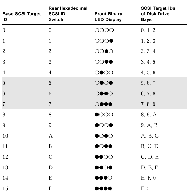
The position of the binary display indicates the base number (first number) of the three drive sequence. See the pull-out card or the Binary SCSI ID LEDs section. |
No action is necessary. |
Note: If a disk drive is under an unusually heavy load (for example, if the drive is being reformatted), the Disk Drive LED might be unlit for a long period of time, even though the drive has not failed. You should see a message in your console window telling you that the disk drive is offline if the disk drive has truly failed.
The disk drive SCSI ID numbers are assigned in sequences of three numbers in a row. The first number in the sequence is the base address. The base address is the number used to set the SCSI toggle switch on the back of the storage enclosure and is represented in binary format on the top row of disk drive LEDs on the front of the storage enclosure.
Note: The shaded rows of the table represent SCSI ID sequences that cannot be used because SCSI ID 7 is assigned to the SCSI controller. Some servers reserve SCSI ID 6 for use by CD drives and IDs 0 and 1 for internal drives.


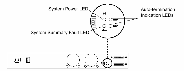
The System Power and System Summary Fault LEDs give the same diagnostic information as the System Power and System Summary Fault LEDs at the front of the enclosure.
The Auto-termination Indication LEDs indicate if the StorEdge S1 storage enclosure is part of an UltraSCSI, wide SCSI, or narrow SCSI daisy-chain. They also indicate the enclosure's position in the daisy-chain.
|
Auto-termination Indication LEDs and Their Meanings
|
||
| High | Low | Meaning |
| Off | Off | The StorEdge S1 enclosure is the first device in the UltraSCSI or wide SCSI daisy-chain; another device follows the StorEdge S1 enclosure. |
| On | On | The StorEdge S1 storage enclosure is the last or only device in the UltraSCSI or wide SCSI daisy-chain. |
| On | Off | A narrow SCSI device follows the StorEdge S1 storage enclosure in the daisy-chain. |
| Off | On | N/A |
|
Legal Terms Privacy Policy Feedback | |||