
| Sun System Handbook | Home | Systems | Components | General Info | Search | Feedback | |
|
|
||
|
| ||
 |
|
|||||||||||||
|
|
|||||||||||||||||||||||||||||||||||||||||||||||||||||||||||||||||||||||||||||||||||||||||||||||||||||||||||||||||||||||||||||||||||||||||||||||||||||||||||||||||||||||||||||||||||||||||||||||||||||||||||||||||||||||||||||||||||||||||||||||||||||||||||
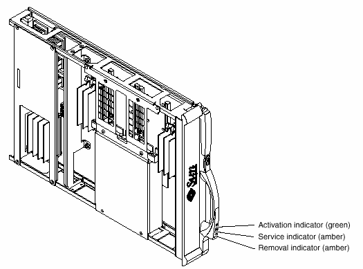
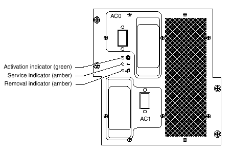
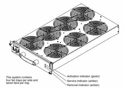
Sun Fire 15K LEDsHardware IndicatorsThe LED indicators provide current status information about the component directly associated with the indicator array. Indicators are arranged in a straight line, horizontal or vertical, with the green LED on the left or top. Component LED StatusClick on the Component links for LED locations and more information. Failure of the service LED to transition from ON to OFF within 60 seconds after insertion indicates a power-status control fault (except for CPU Board and Power Supply LEDs).
Centerplane Support Board | |||||||||||||||||||||||||||||||||||||||||||||||||||||||||||||||||||||||||||||||||||||||||||||||||||||||||||||||||||||||||||||||||||||||||||||||||||||||||||||||||||||||||||||||||||||||||||||||||||||||||||||||||||||||||||||||||||||||||||||||||||||||||||
| System Control CPU Board Indicator Function Descriptions | |
| Indicator Functions | Description |
| Alarm | Not used. |
| Ready | Component ON and board is READY. |
| Reset button |
Global reset to the SC CPU and PCI reset to the SC. Using the RESET button will reboot the operating system on the SC if the appropriate open boot PROM environment variables have been set. |
| Abort button |
Resets the CPU. When the ABORT button on the front panel of the SC CPU (CP1500) board is pressed, an external initiated reset (XIR) is generated to the CPU module, returning the CPU to a known start up state. No other devices are affected by this reset. |
CAUTION: Using the SC CPU reset and SC CPU abort hardware buttons may corrupt the operating system disk if the operating system has not been properly shut down.
System Control must be present and powered on before the SC peripheral board can be powered on.
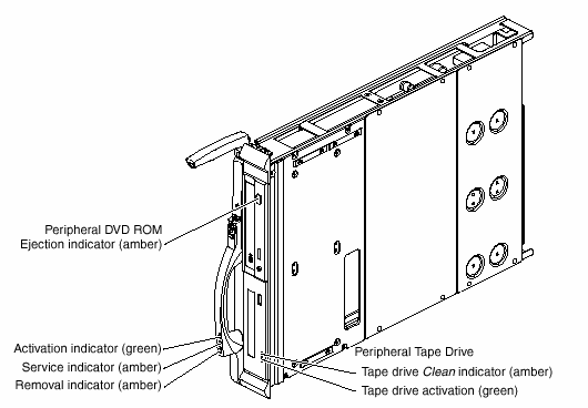
| System Control DVD Peripheral Indicator Function Descriptions | |
| Indicator Functions | Description |
| Blinking (.8 second intervals) | Busy |
| OFF | Idle |
| OFF | No disk |
| ON | Error |
| Blinking (1.6 second intervals) | Audio playback |
| ON | Data transfer |
| System Control Tape Peripheral Indicator Function Descriptions | ||
| Indicator Functions | Description | |
| Tape Indicator | Green flashing and amber OFF | Loading or unloading |
| Green fast flashing and amber OFF | Reading and writing | |
| Green ON and amber OFF | Tape is loaded and ready | |
| Green ON or OFF and amber flashing | Clean tape drive | |
| Green ON or OFF and amber ON | Error | |
| Cleaning Mode | Green fast flashing and amber OFF | Cleaning in progress |
| Firmware Upgrade Mode | Green fast flashing and amber fast flashing | Firmware is downloading (auto ejection when complete) |
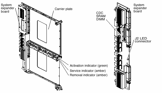
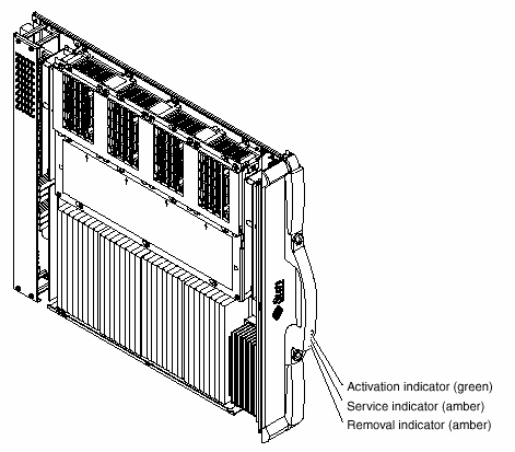
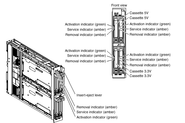
|
Legal Terms Privacy Policy Feedback | |||